 |
|
The NC controller NBY-15 |
| |
|
The NC controller NBY-15 |
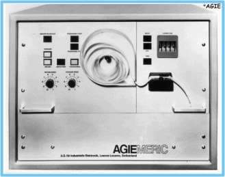
The AGIEMERIC NBY-15, the numerical controller, was the actual heart of the complete unit and a real masterpiece, considering the year of the development and the budget that was made available.
For the wire EDM machine, components and features had to be conceived and developed which were not available and necessary on other already existing controllers. One of these features was the return-motion memory, which kept track of the last 256 steps (Ľ Kilobyte!) in both X and Y direction, so that the same sequence of steps could be executed in reverse direction in case of a short circuit. On a conventional or ram-type EDM machine, the erosion direction is simply inverted in case of a short circuit. If the DEM 15 was not able to eliminate the short circuit automatically, most frequently caused by debris in the cutting gap, the machine simply stopped, and the machine operator had to intervene and solve the problem manually. The return motion was executed without erosion current, only with a reference tension, to avoid that the cutting gap was widened. Once the short circuit was eliminated, either automatically or manually, the renewed forward motion was also executed without erosion, for the same reason.
 |
|
The "Base-Circle" |
|
|
The values ΔX and ΔY |
Because of the then high costs of hardware, no circular interpolator was used in the controller to compute the movements along circular arcs. Instead of that, an ingenuous method was conceived to replace the circular interpolator.
A so-called fixed-value memory was once and for all
computed, for a radius of 262'144 mm (218),
which determined the necessary X and Y motions necessary for each single degree
between 0° and 44° along that radius. These values were first optimized
with extensive test-cuts and memorized on a single
printed circuit board with a very large series of diodes!
This means, that the X and Y motions were memorized for said
circle between 18° and 19°, 22° and 23°, etc.. These values were named Delta
X* and Delta Y* respectively (ΔX* and ΔY*, * for the corresponding
angle, e.g. ΔX18 and ΔY18,
ΔX22 and ΔY22, etc.). The angles above
45° were deducted by simply changing the signs of the X and Y increments. The number of steps which were necessary for the required
radius were computed by dividing the current Delta X* and Delta Y* by 218,
and multiplying it with the radius to be executed. It is quite obvious that such
a division always created residual decimal places which could not be executed by the
machine. These values were memorized in a residual value memory, consisting of a
ferrite-ring matrix. These values were taken into consideration during the next
operation, to keep the rounding errors as low as possible.
This method implied that the smallest angular increment that could be programmed was 1°, smaller portions could only be executed with quite intensive computing tricks, only developed later on by the programming crew (see programming).
The program was punched into an 8-channel, 1" wide paper tape, which was read into the controller via an electromechanical reader. The movements were always, save for very few exceptions, computed for the centerline path of the wire, the controller being equipped with a tool offset feature, which allowed the offset to be generated by the controller. This offset generally consisted of the wire radius, the sparking gap and a possible allowance for a clearance between punch and die, an over or undersize of an electrode, or other dimensions to be considered. The offset could be selected via a rotary switch, between ±000 and ±999 µm (0.001 mm). The real limit of the offset was not limited by these dimensions, but by the smallest radius contained in the program.
A further limitation of the offset was that only contours which were perfectly tangent could be corrected, meaning that the start point of one segment, straight line or circular arc, had to be absolutely identical to the end point of the preceding one. As the controller was constructed for incremental input, this fact often constituted major computing problems. If the selected offset value was too large or the tangency condition was not respected, the machine took off on a very large radius, invariably moving the machine onto the travel end-switches.
To be ready for possible return movements due to short circuits, the controller always read three sentences or increments ahead, these being stored into a buffer memory, this also to adjust for the slow reading speed of the electromechanical reader.
The first controllers were not yet equipped with take-up reels for the punched tape, the once machined portions of the tape were simply collected into a container of acrylic glass.
 |
|
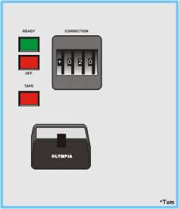
| The left panel of the NBY-15 | The right panel of the NBY-15 |
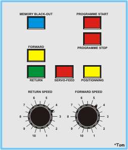
On the front panel of the NBY-15, the following dials, switches and indicators were placed (see image above):
One indicator "MEMORY BLACKOUT", end of return-memory reached,
One indicator "FORWARD", erosion in programmed direction,
One indicator "RETURN", movement during short circuits, returning along the last executed path,
One indicator "SERVO-FEED", movement with reference tension from the return-memory after a short circuit, without erosion,
One indicator "PROGRAMME START", normal erosion process,
One indicator "PROGRAMME STOP", to show interruptions,
One rotary dial each for "FORWARD SPEED" (real forward speed) and "RETURN SPEED" (real return speed during short circuits),
One indicator "READY" when the machine was ready to be started,
One indicator "OFF" showing an interruption or the end of the program,
One indicator "TAPE" if a reader error occurred or no tape was placed in the tape-reader.
On the back of the controller, several switches and dials were placed, to select the scaling factor, in several steps, both up and down, and to invert the sign of execution of the movements along the single axes, allowing rotations and mirror images to be produced with the same program. Another switch allowed the program to be executed in "dry run", to check everything without erosion.